In Part 1 and Part 2 of MBE for Electronics series, we captured the high-level functional objectives and architecture of our system using SysML and a Model-Based Engineering approach. In this part, we'll study how the SysML model connects to mechanical CAD (MCAD) and simulation tools through an MBE interoperability platform, Syndeia, and how the graph network of connections between models in different tools might be visualized.
Introduction
Dramatic advances in commercial electronics have been powered by engineering software that closely couples design, analysis, and manufacturing. This enables seamless cooperation between electronics OEMs, silicon foundries, packaging houses and contract manufacturers, with new product prototypes available in weeks rather than months or years. If MBE practices are to have an impact on electronic products, they must be able to match the same kind of efficient interchange between software tools. In this part of the blog series on MBE for Electronics, we will look at how tools like Syndeia, Intercax’s MBE platform, can make this happen.
Integrating the SysML Model with Other Engineering Applications
A SysML model can be a valuable first step in the conceptual design of a new product, but it is not intended to replace the detailed design and analysis tools or to store all product data. As the engineering process continues, many additional tools and repositories come into play, including CAD, PLM, ALM, simulation and project management, typically from multiple vendors.
The problem arises that the product models in these separate tools will become inconsistent over time and errors will creep into the design. Powerful dynamic mechanisms are required to mitigate this, leading to the development of the Model-Based Engineering (MBE) concept. Note that MBE does not mean the use of models in engineering; it implies a single product model distributed over multiple tools and repositories.
Syndeia, from Intercax, is a platform for the practice of MBE. It uses a system architecture model as a central hub and connects SysML elements to elements in PLM, CAD, ALM (application lifecycle management), project management, requirements, simulation and other engineering tools. SysML is an effective medium for building a high-level roadmap of the system because it provides a rich language for connecting structure, behavior, requirements and analysis concepts, concepts that can map to corresponding concepts in more specialized tools.
With Syndeia, the elements remain connected, linking the models in different tools into a single system model, the ultimate objective of MBE.
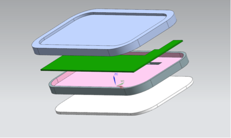
Figure 1 CAD model, main phablet mechanical components
For example, the CAD models of the phablet mechanical packaging components, shown in Figure 1, can be opened directly from the corresponding blocks in the SysML model, once Syndeia has created the connection. If the CAD model is parameterized, the parameter values can be updated between CAD and SysML models when they change, allowing periodic re-verification of requirements as the design evolves.
Analysis is a critical part of MBE and should be incorporated into the system model as early as possible
- To evaluate possible system variants
- To explore system risk
- To verify requirements on an ongoing basis
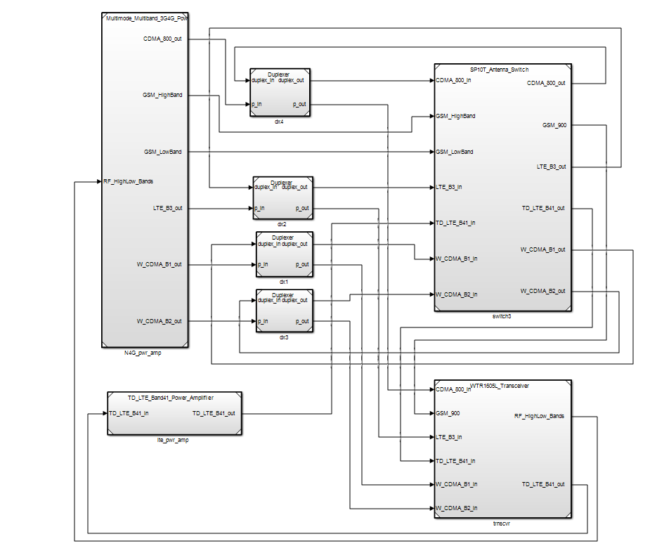
Figure 2 Simulink model of a portion of the radio subsystem model, created from the SysML model by Syndeia
One MBE approach supported by Syndeia allows parts of the system architecture model, for example, the radio subsystem shown in Part 2, is to be transformed into a Simulink block structure, part of which is shown in Figure 2. The block structure, ports and connectors are carried over into Simulink (The Mathworks, Inc.), where the Simulink analyst adds MATLAB code and internal structure as needed to create an executable simulation. Syndeia allows the top-level architecture of the two models to be compared and, as needed, updated, as the SysML and Simulink models evolve.
Visualizing the Total System Model
As the number of connections grows, our ability to understand the scope and complexity of the total system model and to identify extended linkages between elements diminishes. We need to be able to view the system model in order to use it effectively.
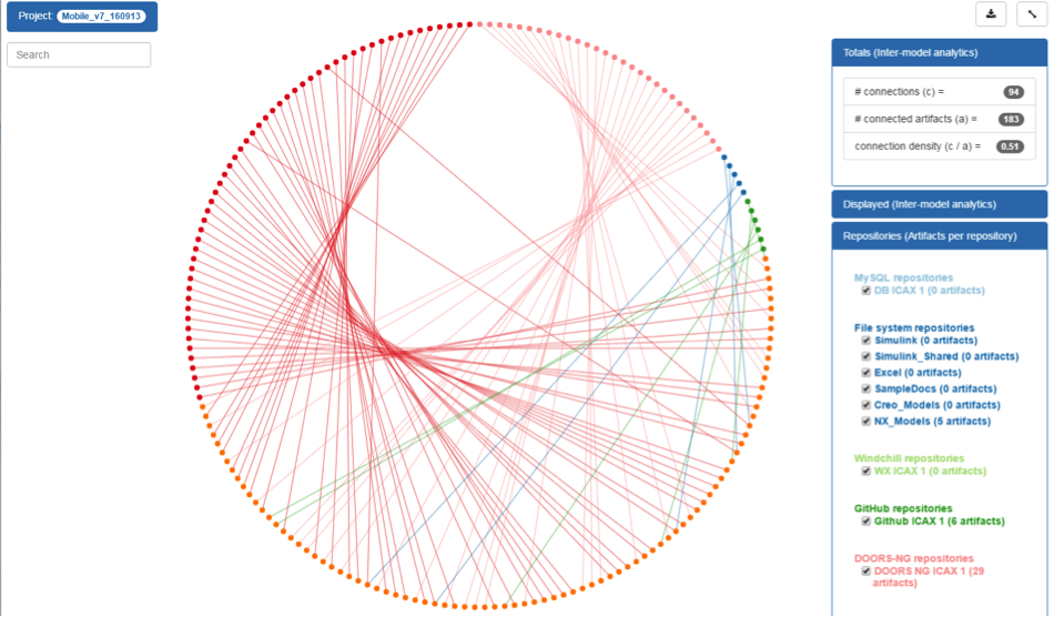
Figure 3 Chord plot of Inter-model Connections – Global Visualization
Figure 3 shows a global view of the inter-model connections in a chord plot. The upper right box reports that 183 elements are connected by 94 Syndeia-managed connections. The elements on the periphery of the circle represent SysML (orange), Siemens Teamcenter (green), NX (blue), GitHub (green) and DOORS-NG (pink) elements. In our case, system requirements were imported from DOORS at the beginning of the project and the Teamcenter PLM bill-of-materials was generated from the SysML block structure when the functional design was complete. In both cases, changes at one end of the connection may be updated to the other. GitHub and NX connections were created manually between pre-existing elements. Refer to and download our paper from the 2016 AIAA conference on use cases and examples for interfacing system architecture models with CAD geometry (see the Papers section at the end of this post).
Using this, system engineers can see at a glance the types of elements being connected and the density of connections in the current state of the model. They can search and filter the graph for model elements based on id, type, parent repository, or other criteria.
Next Steps
In this blog post, we have described how the SysML architectural model can be linked to detailed design and simulation models. Much more work needs to be done in this area, especially in interfacing MBE to ECAD, wire harness, and electronic simulation tools. However, in Part 4 we will redirect our attention, looking at the larger network of which the phablet is a node, and how MBE can specify the relationships involved.
SysML Models:
We are making SysML models of the Phablet example available openly to review and provide us feedback. The models are copyrighted by Intercax. You are free to reuse and adapt the models if you add the following reference in your model: "Adapted from Intercax Phablet model available at https://intercax.com/blog/2017/04/12/mbe-for-electronics-part-1"
SysML Models:
- IBM Rhapsody model: Phablet_Cellular_Network_Example.zip
- Magicdraw model: Phablet_Cellular_Network_Example.mdzip
Technote: Applications of MBE to Electronics
Papers:
- AIAA 2016 paper
- INCOSE IS 2016 paper
Related posts:
- MBE For Electronics | Part 1
- MBE For Electronics | Part 2
- MBE For Electronics | Part 3 (this post)
- MBE For Electronics | Part 4