Electronic product developers have extraordinarily powerful software design tools at their command, but high-level hardware and software architectures and requirements are often handled more informally. Modern MBE tools can help formalize this part of the process, particularly if they can connect easily to more detailed models as the product design evolves. In this SysML v2 demo, we will continue the SysML conceptual design of our phablet, with connections to other tools discussed in Part 3.
Building a SysML Model for an Electronic Product

Figure 1 Phablet requirements specifications
Based on the high-level functional objectives captured in the use cases and a range of other technical, market, and regulatory considerations, systems engineers develop a set of product requirements. Figure 1 shows a partial list of these. These can be created and managed in the SysML tool or (as we will show in the next part) created in a specialized requirements management tools and brought into a SysML model.


Figure 2 Block definition diagrams showing the top-level structure and a breakdown on one subsystem
Figure 2 shows a partial structural decomposition of the major subsystems, one of which, the Radio Subsystem, is further decomposed. Our example of phablet structure is adapted from an analysis of a real commercial product available here.
A SysML internal block diagram, as shown in Figure 3, shows how the signals are routed between components, which must differentiate between a wide range of frequencies and formats.
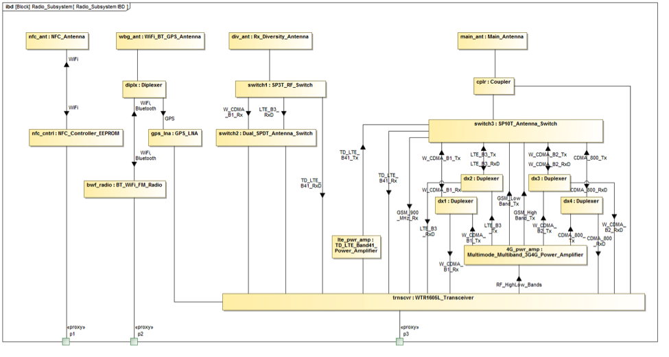
Figure 3 SysML internal block diagram for the phablet radio subsystem, showing the different RF signals and components
Ultimately, we come full circle and the modeling tool allows us to connect the structure back to the requirements in Figure 4, which displays <<satisfy>> relations between the Connectivity Specification requirements and the item flows in Figure 3. All connectivity types are represented by at least one item flow in the radio subsystem.

Figure 4 Satisfy matrix between connectivity requirement and signal flows in the radio subsystem
Among other benefits, this allows us to verify that all connectivity requirements are supported in our high-level model.
Next Steps
In Parts 1 and 2, we have seen a SysML-based MBE approach or SysML v2 Demo for the high-level conceptual design and validation of our phablet. In Part 3, we will go beyond the sysml 2.0 model to show how it connects to MCAD and simulation tools through an MBE interoperability platform, Syndeia, and how the graph network of connections between models in different tools might be visualized.
SysML Models:
We are making SysML models of the Phablet example available openly to review and provide us feedback. The models are copyrighted by Intercax. You are free to reuse and adapt the models if you add the following reference in your model: "Adapted from Intercax Phablet model available at https://intercax.com/blog/2017/04/12/mbe-for-electronics-part-1"
SysML v2 in Action:
- IBM Rhapsody model: Phablet_Cellular_Network_Example.zip
- Magicdraw model: Phablet_Cellular_Network_Example.mdzip
Technote: Applications of MBE to Electronics
Related posts:
- MBE For Electronics | Part 1
- MBE For Electronics | Part 2 (this post)
- MBE For Electronics | Part 3
- MBE For Electronics | Part 4