Intercax is always excited to work with organizations new to Digital Engineering. One such organization (whose identity we are not permitted to share) faced a challenge modernizing a workflow originally designed to build wooden toy trains to the production of modern video games. They wished to apply Digital Engineering to the integrated and concurrent development of both a new production facility and the products to be built in it.
The client organization had a surprisingly modern engineering software toolset for an old-line manufacturing concern. Requirements are initially developed in IBM DOORS Next Gen. Current versions are selectively transformed into Cameo Enterprise Architect (Dassault Systemes), where the architecture of both the production facility and the product is established. Facility design is detailed in Siemens Teamcenter and ECAD product designs are stored in Zuken DS-E3. The initial digital thread schema is summarized in Figure 1; future extension to additional tools in under consideration.
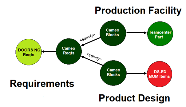
Figure 1 Proposed Digital Thread Schema
After an extensive evaluation, the client selected Syndeia to provide the core services for their integrated design environment. Selection criteria included
- Rapid ramp-up with all tool integrations and use cases supported out-of-the box (project deadline of December 24th critical),
- Ease of customization and configuration (client has a sleighful of unique characteristics),
- Rich graphics for system visualization,
- Scalability to support a global distribution system,
- Plus, our Applications Support team has all been on the “Nice List” for many years.
Figure 2 displays a requirements diagram in SysML created by a Syndeia model transformation from a DOORS NG repository to Cameo. Requirements remain individually linked so that updates to DOORS can easily be passed to the SysML model.
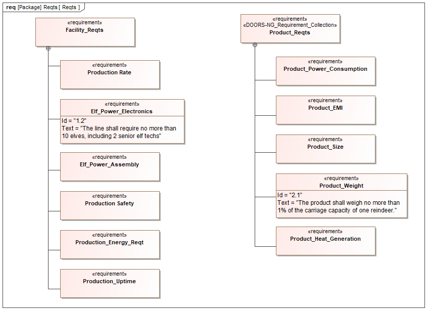 Figure 2 Product and Facility Requirements (partial)
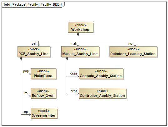
Both production facility and product architecture were initially developed in SysML, related back to the requirements by <satisfy> links. Facility elements (Figure 3) were transformed into Teamcenter for detailed design/procurement, with those elements updated back to the system model in Cameo as required. A similar process was used for the product design, with ECAD model in DS-E3 transformed into the system model.
The digital thread created by these transactions is stored as a configuration-managed graph, which can be queried and visualized in the Syndeia Web Dashboard, which the “Big Guy” and his management team can use to monitor the project real-time. A simple Gremlin graph query to display all the inter-model connections at an early stage of the project took on an unexpected configuration, as shown in Figure 4. Intercax is still exploring how the client might have achieved this non-standard layout.
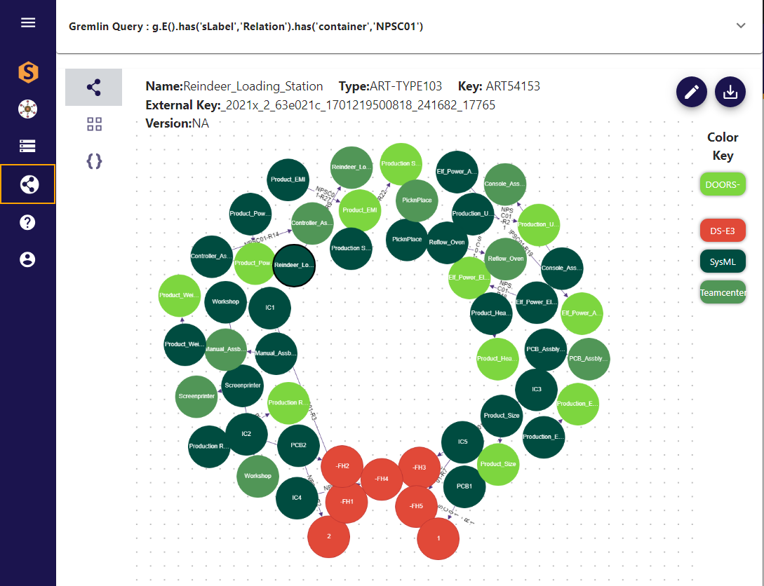 Figure 4 Digital Thread for High Arctic Project
On a completely unrelated note, the warmest of Holiday Greetings from all of us at Intercax to our friends around the world, with hopes for Peace and Prosperity for all people of goodwill.