I recently had a thought-provoking discussion with a Computer-Aided Design (CAD) expert about Model-Based Systems Engineering (MBSE). While I was prepared to show Syndeia’s features for connecting SysML models with NX or Creo, his concerns were more fundamental. First, he pointed out that our examples in the introductory videos were “trivial” and not how people actually designed components with these tools. I readily admitted my personal limitations as a CAD designer, but that Syndeia could work with more complex and realistic designs.
But then he went on, “I don’t see why I would want to pull a CAD design into SysML in the first place. What would SysML do with a CAD assembly with thousands of parts, like a complete aircraft design? Could the MBSE tools even handle it?” Our discussion progressed from that point and I think I helped him find some answers for those questions. However, it did make me more aware that many engineers do need some basic questions about use case addressed on first contact.
In an earlier blog post, I discussed MBSE use cases in general terms, starting from the assumption that designing a new system from scratch was not the only use case, probably not even the most common one. Other scenarios for applying MBSE are equally important and the SysML-CAD interface plays a potentially important role in many of them:
- Reverse Engineering
- Variant Evaluation
- Failure Analysis
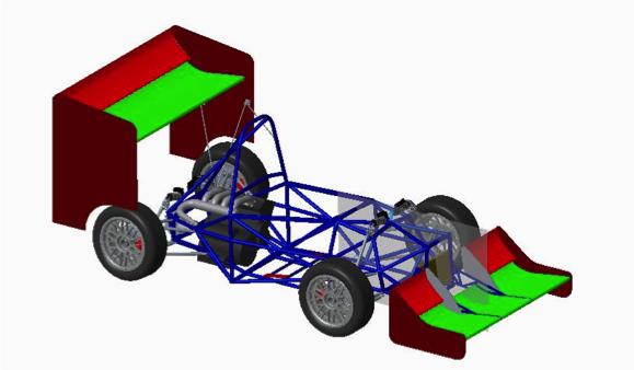
PTC Creo Race Car Example
Architecture and Design
Under the classic V Model of systems engineering, requirements are developed at the beginning of the development process and verified as the process proceeds. At every stage, the systems engineers (SEs) interact with the CAD designers. Initially, the SE must distribute the requirements to the appropriate designers. Requirements for mechanical design might include overall size (bounding box) or mass, as well as detailed geometry considerations: reference planes, keep-out zones, center-of-gravity restrictions. These rarely lend themselves to simple text statements. Accompanying documentation such as sketches are subject to misinterpretation. In addition, requirements can change during the project, compounding the problem.
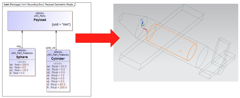
An alternate approach with MBE platforms such as Syndeia is to supply the requirements directly as a native CAD file in the designer’s tool. The example below defines the payload volume and center of gravity location in a SysML block structure. Syndeia takes this structure and creates the starting elements in NX, from which the designer begins his work. Because the connection between the SysML and CAD elements is maintained, the system engineer can use Syndeia to compare current model versions in the SysML model and the CAD tool and intervene if they differ.
When the time comes to verify requirements, the SE must draw upon the CAD designers’ work to check, for example, size and mass, individually or rolled up by assembly. One goal of MBE is to run verifications frequently and efficiently throughout development. This requires quick access to current design parameters. Using Syndeia, the CAD design can be pulled into the SysML model, and mass properties and parameter values updated in SysML with a simple sync command.
Variant Evaluation
Some system models are created with a specific purpose in mind, for example, to evaluate different system variants for fitness of purpose. SysML simplifies the composition of allowable system variants, especially system variants that differ topologically or architecturally rather than by parameter values. These system models often include common analysis blocks that apply to each variant. To execute these analyses, the parameter values from CAD models of the variants may be required. As described above, persistent connections between CAD and SysML models facilitates the transfer of design parameters for analysis and verification against requirements.
Reverse Engineering
By reverse engineering, I mean taking product data from older products and bringing it into MBSE format. Organizations practice this for a variety of reasons
- To document existing products
- To capture architectural information from older products in re-useable model-based form
- To develop their modeling skills
This is one case where the ability of Syndeia to decompose a complex CAD assembly diagram into a corresponding SysML block structure can save a significant effort. The SysML block structure becomes the basis for capturing the deeper knowledge of the product design, the relationship between function and design, for example, that might otherwise be lost when the original developers have retired.
Failure Analysis
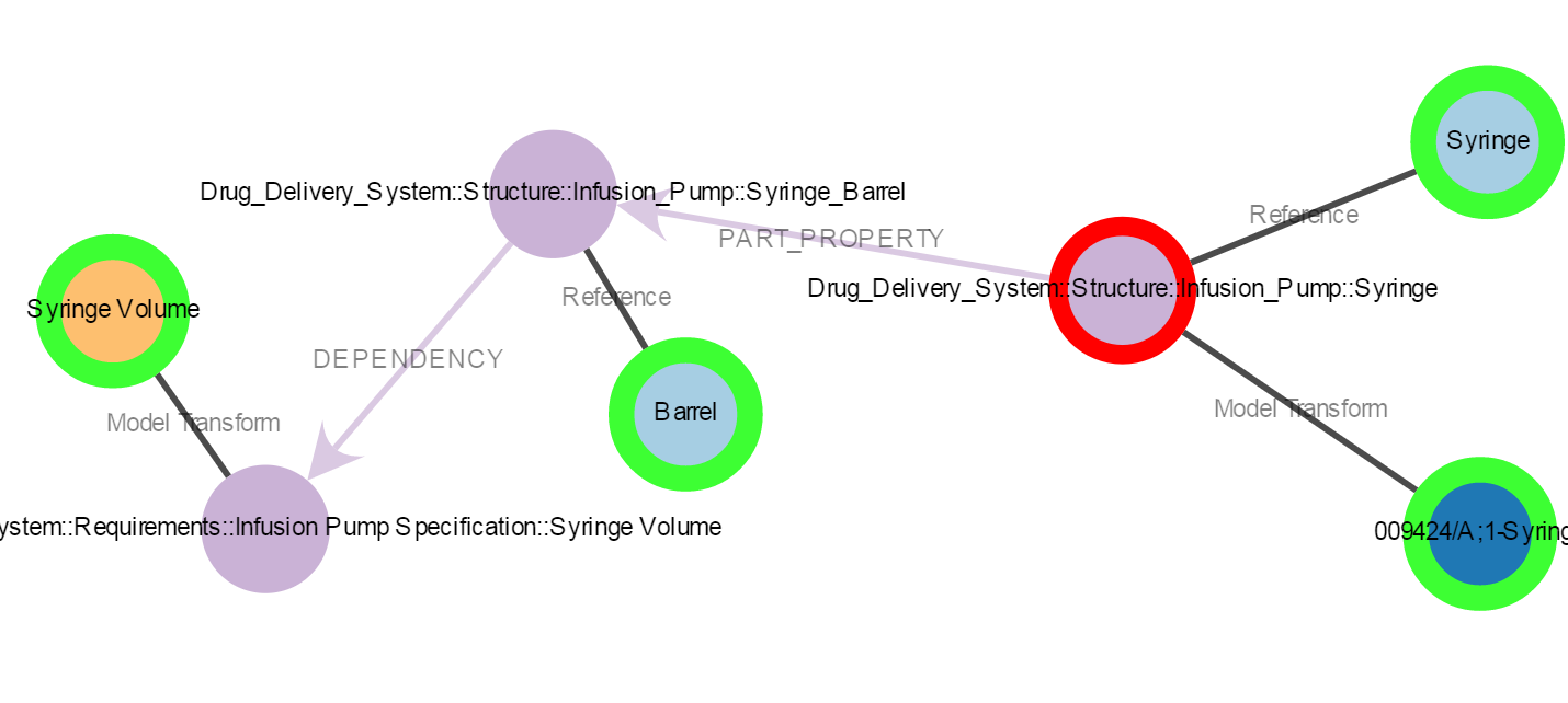
A critical tool for diagnosing system failures is a means of navigating quickly across the system model, jumping between tools and product data repositories along easily identifiable paths. This is especially important in diagnosing and correcting field failures where time is of the essence. In the figure below, we see a visualization of the connections between SysML blocks, requirements, PLM items and CAD files for a syringe assembly in a medical infusion pumps. Using Syndeia, the SE can follow linkages and open files from a single platform, tracing from function to structure quickly to identify root causes.
Learn More
For a more detailed discussion of MBSE and CAD, download the paper by Intercax and NASA JPL from a recent AIAA conference. In its discussion of use cases and application to the Europa Clipper Mission, the paper reviews some of the challenges in applying these new approaches to large-scale projects. These include
- Scale - Can existing MBSE tools handle the complexity of real systems?
- Scope – What level of detail from the CAD files is necessary in the SysML model?
- Access – Who can access the Total System Model and what licenses are required?
- Data Governance – Who owns the shared product info and how can it be modified?
- Parameterization – How important are parameterized CAD models for facilitating richer communication between SEs and mechanical designers?
- Different Abstractions – If the SE thinks in terms of logical subsystems and the CAD designer thinks about physical assemblies, how and where can these be linked?
- Configuration Management and Versioning – What mechanisms are available?
Addressing these issues will be an ongoing process for the MBE community.
Download
For further information/discussion on this topic, please mail us at info@intercax.com.