Introduction
Every system development project has both product-specific and project-specific considerations:
- Product-specific includes product requirements (market, technical, regulatory), product function and hardware and software design
- Project-specific includes organization structure, project requirements, and product development methodology
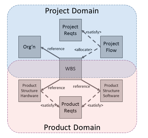 Figure 1 Intersection of Project and Product Domains
The intersection of these two domains is often the Work Breakdown Structure (WBS) which captures the product-specific tasks in the context of the project organization, as illustrated in Figure 1.
Ordinarily, systems engineering is concerned with the first set of considerations, project management, while dedicated teams using specialized tools work on the product. However, the need to coordinate the two is widely recognized. A common model in a common modeling language facilitates this. In this blog post, we will explore how SysML might be used to model the project as well as the product. In the next post, we will show how both product and project information distributed over multiple tools and repositories can be treated as a single system model. The connectivity of this Total System Model (TSM) can be captured in a high-performance graph database and queried by multiple users on the project team.
Modeling the Project Domain
Capturing the project organization in SysML is relatively straightforward, as illustrated in Figure 2. This differs from a conventional organization chart in being model-based rather than a simple image. The top three levels represent organizational groups rather than individuals. Individual group members who might be assigned to projects are represented generically at the bottom level with 1..* multiplicity; specific employees will be represented as specializations or instances of their roles. As we will see in Part 2, employee data can be stored in an external database rather than the SysML model itself.
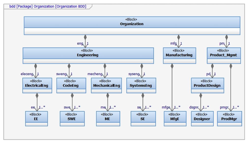
Figure 2 Project Organization Decomposition
In our example, projects are governed by a standard set of project requirements, which are realized in a standard project flow. Figure 3 and Figure 4 show representative requirements and activities from the first phase of the project. Similar activities are created for Product Plan, Product Design and Product Review phases, although in our model, the Product Design phase is driven by product requirements rather than project requirements.
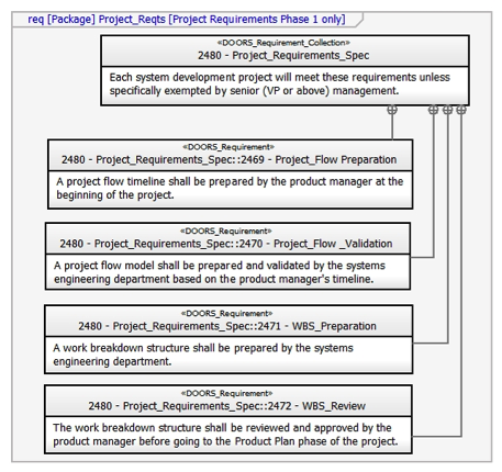
Figure 3 Project Requirements (Phase 1)
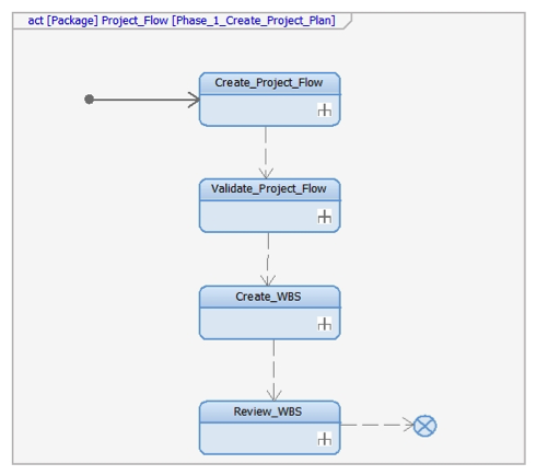
Figure 4 Project Flowchart (Phase 1)
Modeling the Work Breakdown Structure
Our sample model describes the development of an IoT-based product, a locater-pager that registers nearby RFID nametags and directs audible pages to the appropriate location as part of an office-based network. The WBS specific to this development project includes both standard project tasks such as Product_Reqts_Creation and product-specific tasks such as Product_Externals_Design (the design of the outer casing). As with the earlier requirements and activities, each WBS block in Figure 5 can be decomposed into finer levels of detail as needed.
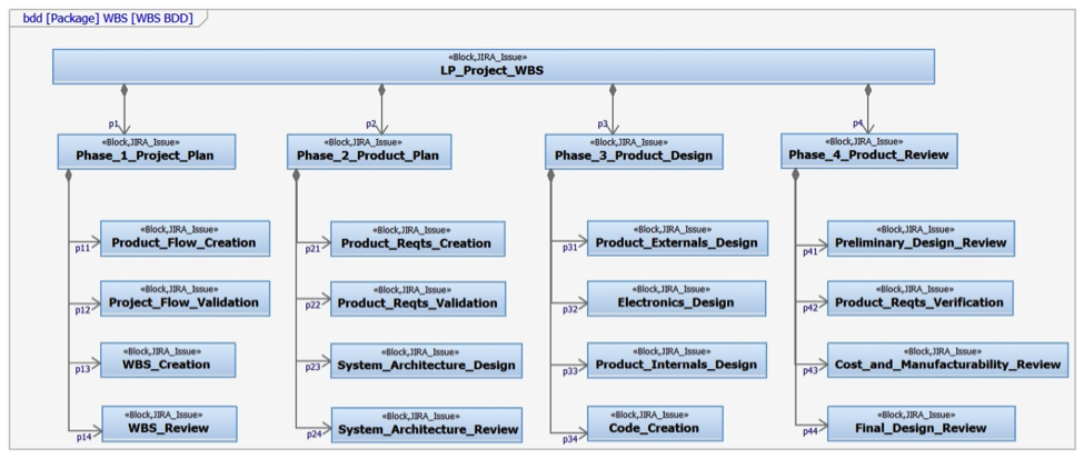
Figure 5 WBS Decomposition
There are potentially many ways to connect the four models in the project domain. In Figure 6, we present one solution, shown for the first phase project elements, using standard SysML relationships
- Project activities representing process flow “satisfy” project requirements
- Project activities are also “allocated” to WBS blocks
- WBS blocks “reference” departments within the organization responsible for the task
When the project structure is instantiated, specific employees within each of the departments can be assigned to the WBS tasks.
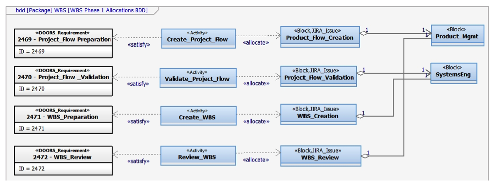
Figure 6 SysML relationships between WBS, organizations, process and requirements
Next Steps
Many software tools and databases will be used in the development of the locater-pager. For example,
- Hardware designers use PLM and CAD
- Software engineers use ALM and simulation
- Systems engineers use requirements management tools
- Project managers use schedule, issue tracking and ERP systems.
The disadvantages of this diverse toolset are the potential for inconsistencies between models, the difficulty in finding needed data, and the problem of identifying extended relationships between requirements, behavior and structure that give rise to emergent system effects. In Part 2 of this discussion, we will show how our MBE platform, Syndeia, creates and maintains a graph of the intra-model and inter-model connections (Figure 7), preserving model integrity and facilitating queries and visualization of the connections.
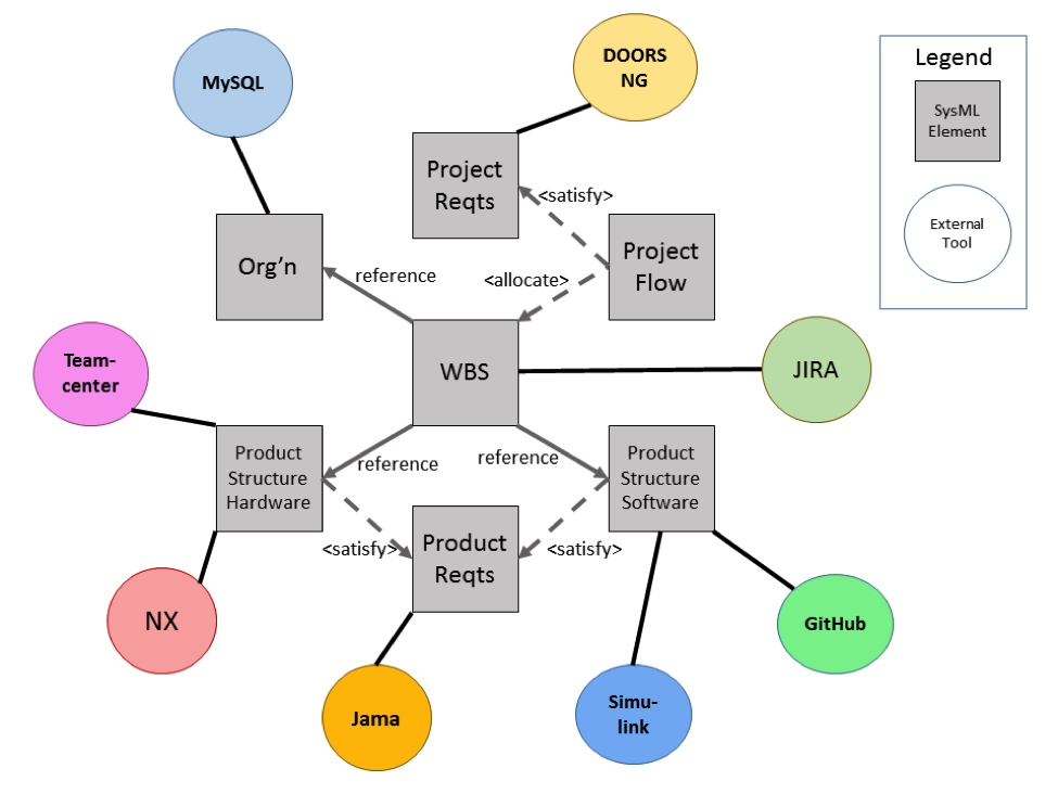
Figure 7 Total System Model concept showing multiple tools and repositories connected through SysML model
Related articles:
- Modeling Project and Product for the Internet of Things (IoT) | Part 1 (This post).
- Modeling Project and Product for the Internet of Things (IoT) | Part 2.
For more information, contact us at info@intercax.com.
If you wish to subscribe to the Intercax website, please drop us an e-mail at info@intercax.com with your Full Name, Company Name and Email Address(es).