As a project moves from architecture definition to component design, new software tools, such as mechanical computer-aided design (MCAD), become part of the engineering process. The impact of component design decisions needs to be continuously evaluated at the system level.
The Syndeia interface for PTC Creo supports a number of use cases from either MagicDraw or Rhapsody, such as the following:
• Search and access Creo models from Syndeia, in local file systems or in PLM repositories (PLM access requires additional interfaces)
• Generate Creo structures in SysML, including part parameters and geometry
• Compare and update structure and parameters as the system evolves.
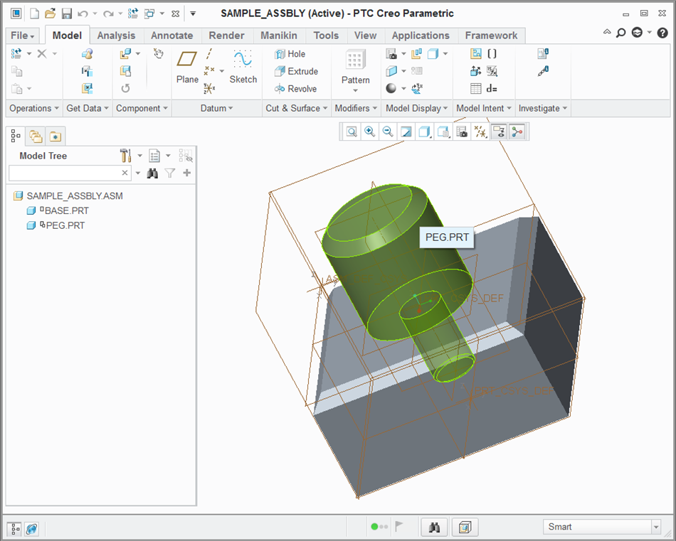
Figure 1: Creo assembly viewed in PTC Creo Parametric 3.0
Figure 1 shows one view of a simple Creo assembly composed of two parts.
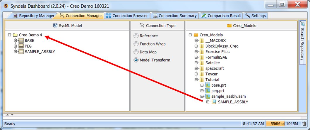
Figure 2: Syndeia dashboard, generating SysML blocks from Creo model using drag-n-drop
Figure 2 shows how this file appears in the Connection Manager tab of the Syndeia dashboard, where we have dragged and dropped the assembly into an empty SysML package.
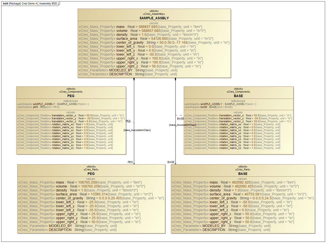
Figure 3: The Creo sample assembly, viewed as a SysML model
The new block structure in SysML is shown in Figure 3. The part structure of the Creo assembly is reproduced in the directed composition relationships in SysML. The mass property (e.g. mass, surface area) and geometry values from the CAD file are carried over as default values in SysML, available for parametric analysis and requirements verification at the system level. The association blocks attached to the directed composition relationships (black diamond arrows in Figure 3) display the translational and rotational coordinate transformations between part and assembly, making a complete picture of the geometry available at the SysML level. Syndeia can compare both structure and values as the SysML and Creo models change, highlighting divergences between the two and allowing the SysML model to be updated on command.
SysML-CAD connections are one part of the broader initiative called Model-Based Engineering (MBE), where barriers between engineering domains are broken down. Giving each engineer on the team better visibility of the system, from requirements to structure to behavior to simulation, can lead to smarter engineering decisions.