Our objective at this stage is to complete the interconnection of urban system blocks in SysML and then to transform that SysML model to an equivalent model in a simulation tool, here Simulink (The MathWorks). The initial step in SysML is to create internal block diagrams (IBDs) showing the parts and their ports and to draw connectors between them. When the SysML model is complex, multiple diagrams are created to limit the number of parts and connectors per diagram to improve interpretability. Since each diagram is a selective view of the same SysML model, models of any complexity can be built by adding additional diagrams. Our complete SysML model, available for download with the final installment of this series, includes sixteen separate IBDs.
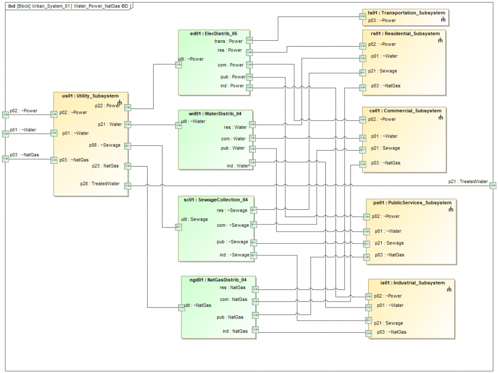
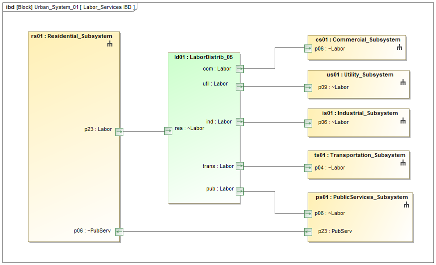
Figure 1 is an example of an IBD from the top-level Urban_System_02 block. It is intended to show the flows of power, water, sewage and natural gas from the Utility Subsystem to the other major subsystems (flows to DataComm and SmartCity subsystems are shown on additional diagrams). Figure 2 shows another IBD from the same level with the flows of labor from the Residential Subsystem to the other subsystems. Additional diagrams show flows of transportation, goods, trash and communications.
One feature of this model is highlighted by the color coding in these IBDs. The tan parts represent the subsystems/services; the green parts are “distribution blocks” representing the allocation of flows between multiple services or the aggregation of flows from multiple services. The use of these distribution blocks is pragmatic. Although SysML allows multiple connectors from one port, this can be a problem during model transform to other tools such as Simulink, which may not permit it.
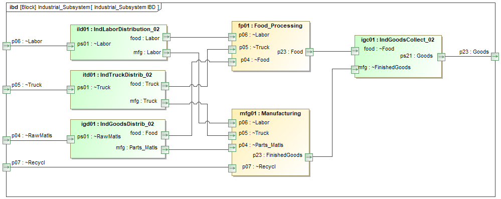
Other IBDs are used to model flows inside the major subsystems. Figure 3 shows the flows of labor/goods/trucks within the Industrial Subsystem. The ports on the diagram boundary represent inputs/outputs of the Industrial Subsystem itself and correspond to ports on parts of that type in higher level diagrams.
Generally, architecture modeling and simulation will be done in different tools, each specialized for the purpose. The challenge arises that these models may be inconsistent, especially as time passes and the models evolve independently. One solution uses Syndeia to transform all or part of the SysML model into a model of similar structure in another tool. Figure 4 shows how the model for the Industrial Subsystem has been transformed into Simulink.
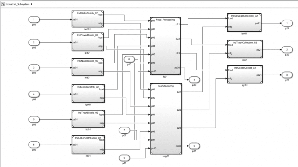
Each Simulink block in Figure 4 is connected to the original SysML block and duplicates its ports and connectors. Syndeia can compare and update the models in either direction as one or both change. Note that the Simulink model created is only the first step in building an executable simulation; typically, a Simulink analyst will add the simulation code to the blocks for the desired analysis. Syndeia maintains traceability between the models as part of the Total System Model.
In the next post, we add connections from our federated models to a JIRA (Atlassian) issue tracking repository for project management purposes. In this and the following posts in the series, we will provide alternative versions for SysML modeling in Rhapsody. Both SysML models will be made available for download with the final installment of the series.
Related Posts:
- MBSE for Urban Systems – Part 1
- MBSE for Urban Systems (Cameo) – Part 2
- MBSE for Urban Systems (Cameo) – Part 3
- MBSE for Urban Systems (Cameo) – Part 4 (this post)
MBSE for Urban Systems (Cameo) – Part 5
MBSE for Urban Systems – Part 6