Our structural model of the urban system is shown in Figure 1, with the overall system treated as a set of subsystems providing resources and/or services: utility, transportation, public services, etc. The Residential Subsystem, for example, provides labor as a service to other subsystems. Each of these subsystems is further decomposed, i.e. utilities include water treatment, electrical power, trash disposal

Note that our purpose here is to illustrate an approach rather than create a definitive urban model. Because of the object-oriented nature of SysML, adding, deleting and modifying model elements is readily accomplished to accommodate differing approaches and objectives.
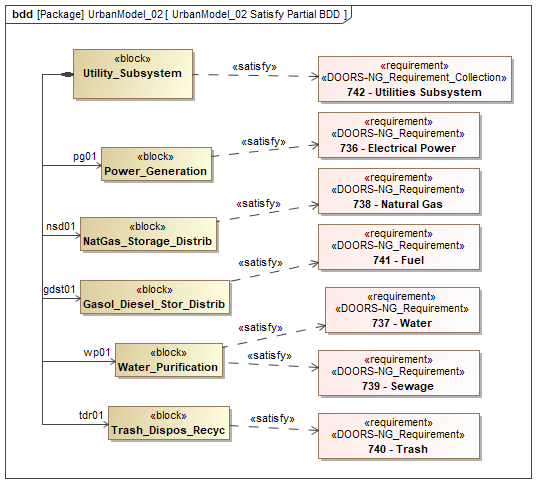
The urban system structure follows directly from the architectural modeling requirements. We can use the <<satisfy>> relationship in SysML to track this in Cameo, as illustrated by example in Figure 2.
The hierarchical composition of the urban
system is just a first step. Of critical
importance is the flow of resources and services across the community. The
prediction and optimization of these flows is our primary objective in creating
the model. In SysML, we capture the
interdependence of the subsystems using proxy ports and connectors.
To begin the process, we identify the flows between the subsystems that we want to specify. For example, the utility subsystem provides energy (as electricity, gasoline and diesel fuel) to the transportation subsystem, which provides transportation services (automotive, trucking, and mass transit) to other subsystems.
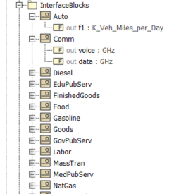
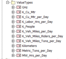
In SysML, we describe these flows in interface blocks, which specifies the possible flows through proxy ports in and out of each block. A partial list of the interface blocks we have created for our model is shown in Figure 3. Because we ultimately wish to quantify these flows, each interface block contains one or more flow properties typed by value types, which provide the units for the flow quantities. We have created our own library of value types for our urban models, shown in Figure 4. The interface block Auto in Figure 3 represents automotive transportation services and has an output flow property typed by K_Veh_Miles_per_Day (thousands of vehicle miles per day). Interface blocks can also represent multiple flows, for example, Comm presents both Data and Voice services.
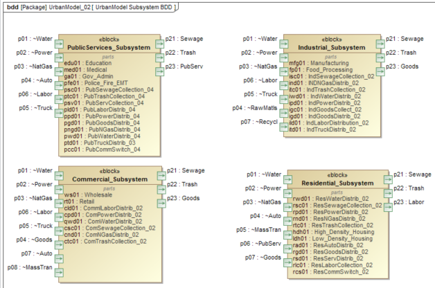
Once interface blocks and value types have been defined, we can specify the ports for each of the subsystems. Several examples are shown in Figure 5. For example, the Industrial Subsystem block is modeled as requiring inputs of water, electrical power, natural gas, labor, and trucking services (for logistics), as well as raw and recycled materials. It puts out goods (both food and manufactured goods), but it also puts out waste as sewage and trash, which the utility subsystem must treat, recycle and/or dispose of. The same assignment of ports is carried out for each of the lower-level services in Figure 1.
In the next post, we will model the interconnections and flows between urban subsystems and use Syndeia to transform the SysML model into Simulink. In this and the following posts in the series, we will provide alternative versions for SysML modeling in Rhapsody. Both SysML models will be made available for download with the final installment of the series.
Related Posts:
- MBSE for Urban Systems – Part 1
- MBSE for Urban Systems (Cameo) – Part 2
- MBSE for Urban Systems (Cameo) – Part 3 (this post)
- MBSE for Urban Systems (Cameo) – Part 4
MBSE for Urban Systems (Cameo) – Part 5
MBSE for Urban Systems – Part 6