Introduction
The energy industry faces a variety of difficult issues:
- Multidisciplinary technology encompassing mechanical, chemical, nuclear, electronic, software and other engineering disciplines
- Need for balance between technological, economic and environmental factors
- High priority placed on energy system security and resilience to natural and man-made disruptions
Because of these challenges, energy system engineers have been early adopters of advanced techniques in model-based engineering (MBE), with engineering tool needs including
- An architectural framework inclusive of structure, behavior, requirements and analysis
- Cross-vendor and cross-discipline interoperability
- Easy-to-use, non-discipline-specific query and visualization capabilities
In a series of blog posts, we will look at some potentially useful approaches through some simple model examples. In this first essay, we look at the design of a new energy generation facility. In the second, we will expand the scope to larger energy systems, including models of generation, distribution, and consumption. Finally, we will consider how modern graph-based models can help expose connections and vulnerabilities in the search for safer and more reliable energy systems.
Case Study 1: Energy Generation System Design – Pressurized-Water Nuclear Reactor
The design and construction of an energy generation facility involves many people, many disciplines, and many software tools, but the high-level roadmap of system architecture was often confined to a set of static, disconnected documents: figures, reports, and spreadsheets. Systems modeling languages such as OMG SysML can create an evolving model of such systems where structure, function, requirements and analysis can interact as peers. The connections between these elements can be tracked and validated, and deficits or inconsistencies identified quickly. Reports and views of the system architecture can be generated at need from the model, with the assurance that they cannot be inconsistent with each other.
We have published a simple nuclear power plant SysML model in three different SysML model authoring tools on our website as an illustration of these principles. Note that these models are not claimed to be accurate representations of real nuclear power generation and are very far from complete. In this blog, we will use a few SysML diagrams from the MagicDraw version of the model to demonstrate the roles that the different diagrams play in capturing structure, behavior, requirements and the relationships between them.
The block definition diagram in Figure 1 represents a structural decomposition of the nuclear power plant with its major subsystems. Examination of the model shows that this one diagram does not represent all elements, for example, sensors and software are shown in a separate diagram, but are part of the same model.
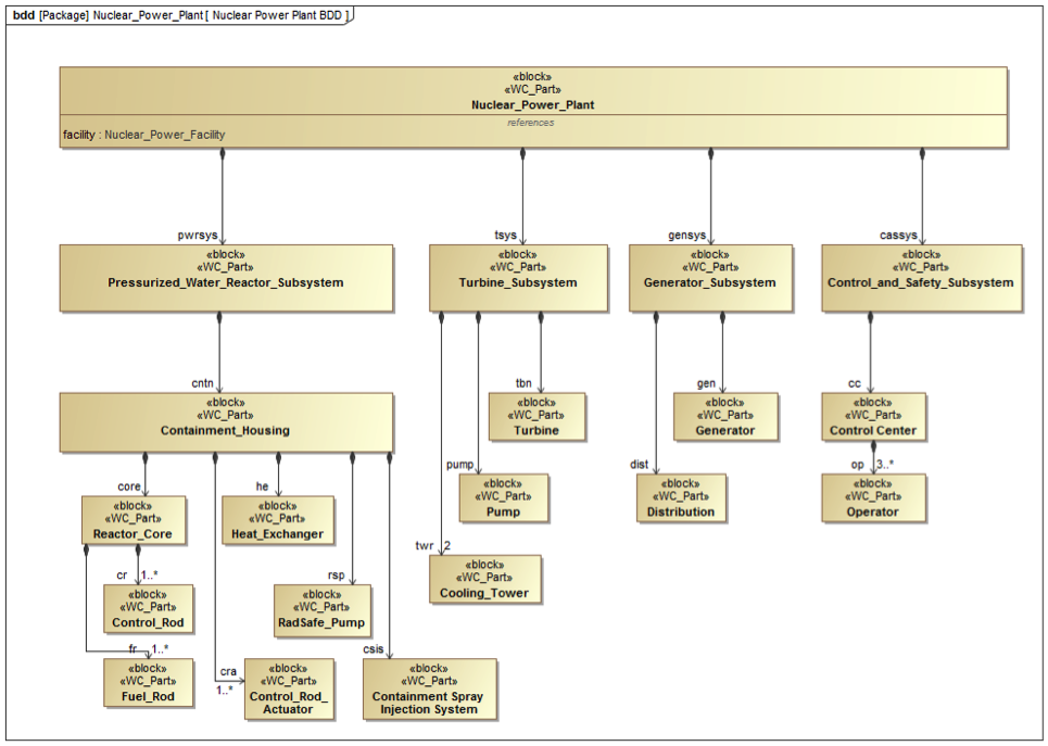
Figure 1 Nuclear Power Plant SysML Block Definition Diagram
Requirements, whether originally generated in SysML, a specialized requirements tool, or MS Office, can be brought into the SysML model and connections made to the model elements designed to satisfy them. In Figure 2, we show a limited subset of those requirements and their relationships.
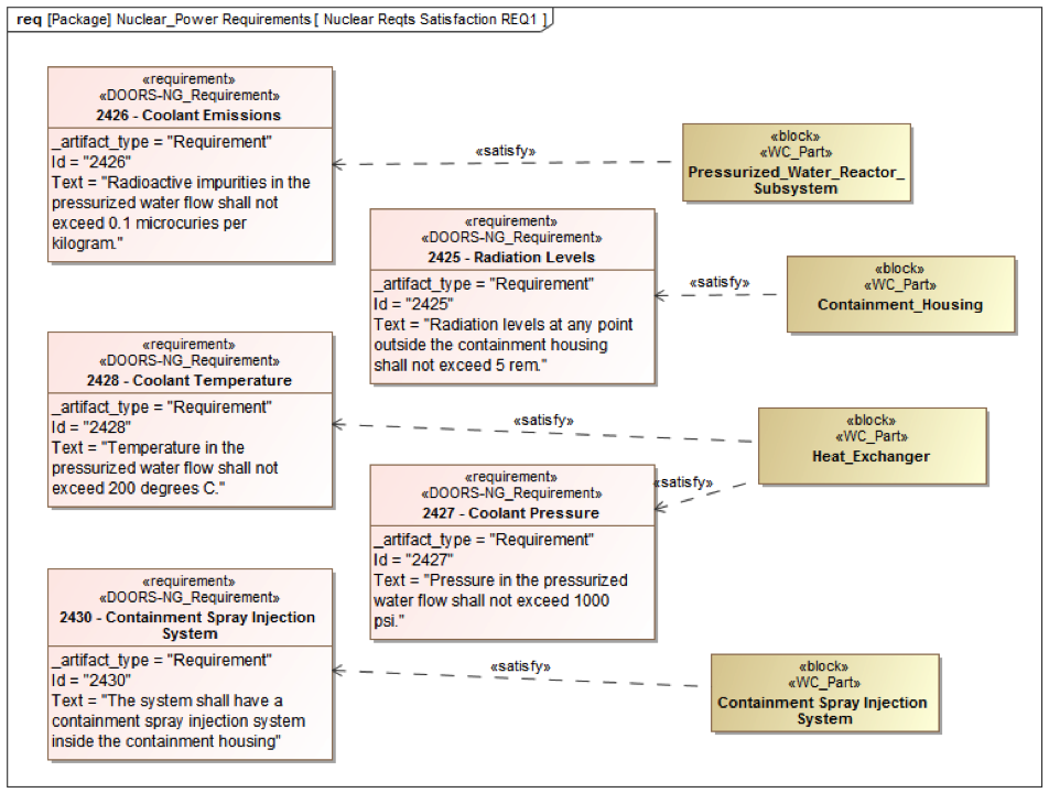
Figure 2 Nuclear Power Plant SysML Requirement Diagram, subset of system requirements and satisfying model elements
Depending on the systems engineering methodology used, system behavior may be modeled prior to or in parallel with system structure. In either case, linking the two is critical to ensuring that the design will support all expected function. Figure 3 shows how high-level functions of the reactor subsystem are allocated to its separate parts, with inputs and outputs on the right diagram edge for connection to downstream functionality.
Figure 3 Nuclear Power Plant SysML Activity Diagram with activity allocations to structural elements
Even the system piping and wiring can be shown in high-level abstraction in a SysML internal block diagram, as in Figure 4. One benefit of this is the check that flows between functions in behavior diagrams (e.g. Figure 3) are supported by physical connections between the components carrying out the functions, and that the interface control documents created are complete and valid.
![]()
Figure 4 Containment Housing SysML internal block diagram
To be maximally useful, the system architecture model should not be unconnected to all the other models in other tools: CAD, PLM, ALM, simulation and project management, to name a few. This transitions us from the domain of Model-Based Systems Engineering to MBE, Model-Based Engineering, where the single system model is distributed over multiple tools and repositories. In Figure 5, we show a visualization from the Intercax MBE platform Syndeia illustrating this.
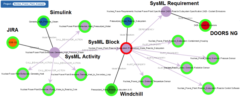
Figure 5 Syndeia graph visualization, partial
Figure 5 was triggered from the central SysML block shown as a gray circle with red border, the Pressurized Water Reactor Subsystem. Some of its nearest neighbors have been further expanded to show a graph including both connections between SysML elements (the gray circles) and connections to model elements in other tools (dark lines connecting to red, green, blue and orange circles). Circles with green borders have the possibility of further expansion.
Next steps
This post was largely abstracted from a longer technical note on MBE for the Energy industry available for download from our website. It is accompanied by the SysML models used to illustrate the discussion, which can also be downloaded. These resources are copyrighted by Intercax LLC and should not be republished without permission.
In the following posts in this series, we will expand our scope. Each power generation facility is part of a utility grid which includes electricity distribution and the supply network that provides the fuel for gas, coal and nuclear generation. The energy grid is deeply embedded in the industrial and transportation infrastructure and a major factor in the economy and the environment on national and international scales. MBE made possible by a new generation of software tools has both the scope and scale to support the energy industry in carrying these responsibilities.
Download
Presentation Deck - Applying MBSE To The Energy Sector
SysML Models - Nuclear_Power_Plant_Example | Nuclear_Plant_Example.eap | Regional_Energy_Model_RHP
Technote PDF - Application of MBE to Energy Engineering
Related Posts
- MBE for the Energy Industry | Part 1 (this post)
- MBE for the Energy Industry | Part 2
- MBE for the Energy Industry | Part 3