 Intercax
 Intercax
We can do the same thing internally for the system components, for example, in the software operations of the DRE. We can begin to decompose the functions of the voting machine using a SysML activity diagram, as shown in Figure 1. This diagram describes the first part of the test and validation activity before voting starts. Each symbol represents a specific action of the DRE software, with the arrows or flows designating the order in which those actions occur. The vertical rectangular channels or swimlanes identify the structural components of the DRE that carry out the actions inside. As with the logistical model we presented in Part 3, the DRE behavioral description in SysML lets us keep the functional and physical models consistent and helps us navigate between them.
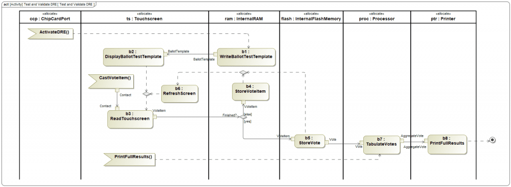
Figure 1 SysML Activity Diagram – Test and Validate DRE Behavior
We can think of Figure 1 as a detailed step-by-step description similar to the sequence diagram in Part 3, this time of the internal software functioning of the DRE. Of course, the actual software is being developed in other tools. These software development environments typically use a configuration-managed repository such as GitHub to save and manage the actual code. In order to connect the functional description in the architectural model to the actual software, we will use Syndeia. In the Syndeia dashboard (Figure 2), we show the SysML model on the left, expanded to show the functional activities. We show the GitHub repository on the right, exposing the corresponding software files. Connections are made by drag and drop. Syndeia can use those connections, for example, to open the GitHub file directly from the SysML diagram by double-clicking on a SysML element, to view the GitHub file in its web interface. Syndeia can also use the connection to let the system engineer check if a newer version of the software file has been committed.
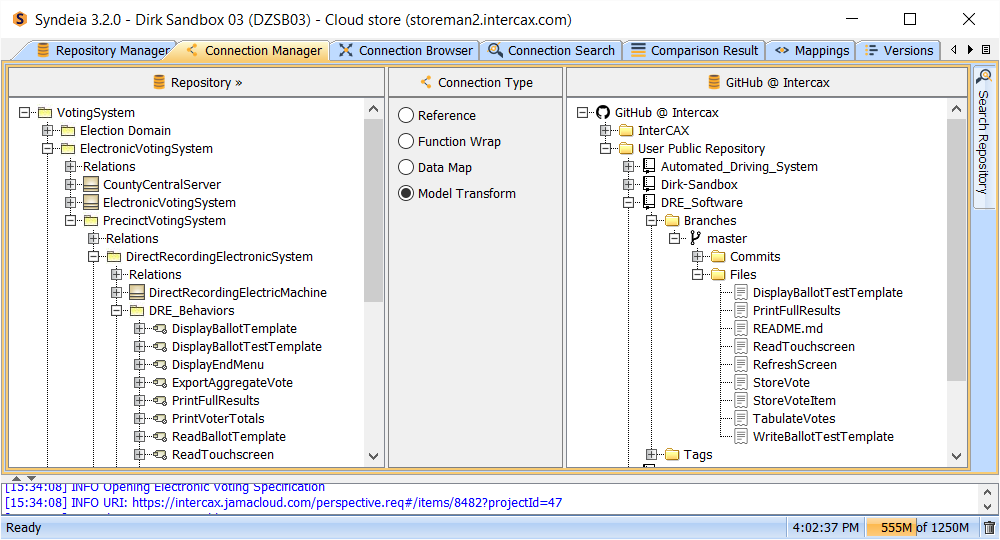
Figure 2 Sequence Diagram in MagicDraw SysML – first phase of elections operations
Similar capabilities are available on the hardware side. If we decompose the DRE into its structural components in the SysML block definition diagram in Figure 3, each of those components can be connected to electrical or mechanical CAD files containing the detailed design as it is developed. For example, a critical mechanical component of the DRE is a locking compartment containing the flash memory card ports. We don’t want unauthorized users, including voters, to have access to those ports to protect the integrity of the DRE machine. If we want to check on that mechanical design, Syndeia can connect that block to a CAD part in Siemens NX and we can open that directly from the SysML diagram. We can track what version of the CAD model we are connected to. We can even share and update certain parameters of the design, like component volume, between the CAD and SysML models.
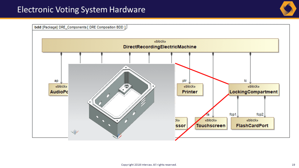
Figure 3 Block Definition Diagram in MagicDraw SysML and LockingCompartment CAD model in Siemens NX
In this manner, the system is designed and specified in a federated set of engineering models. We will use this unambiguous model-based description to facilitate a systematic Failure Mode and Effect Analysis (FMEA) in Part 5 of this series.
Related Posts:
- MBSE for Electronic Voting System Security (MagicDraw) – Part 1
- MBSE for Electronic Voting System Security (MagicDraw) – Part 2
- MBSE for Electronic Voting System Security (MagicDraw) – Part 3
- MBSE for Electronic Voting System Security (MagicDraw) – Part 4 (this post)
- MBSE for Electronic Voting System Security (MagicDraw) – Part 5
- MBSE for Electronic Voting System Security (MagicDraw) – Part 6
