 Intercax
 Intercax
Introduction
In this third post, we build simple rail subsystems from the blocks and control points created before. We offer two examples, a single track with a siding and two parallel tracks with crossovers. These can, in turn, act as parts of larger systems.
This post is the third in a series of blog posts on applying Model-Based Systems Engineering (MBSE) to Railway Control Systems (RCS). We describe some preliminary results for such an approach, showing sample diagrams from several different SysML modeling tools (MagicDraw from No Magic Inc, IBM Rational Rhapsody, and Enterprise Architect from Sparx Systems). These models will be made available for download with the last post of the series, which will also show how the Intercax MBSE platform Syndeia can connect these models with Simulink (The MathWorks, Inc.) for simulation.
Simple Examples of Railway Systems
From simple elements, larger systems can be quickly assembled. The first example is a track with a section of siding. The composition is shown in a SysML block definition diagram in Figure 1, the siding including 4 Blocks, 2 ControlPoint_2Way and 2 ControlPoint_3Way. More helpful may be the internal block diagram of the track connections shown in Figure 2, where b1, b2 and b4 usages of Block form the straight-through section and b3 the siding. The cp4B and cp4C parts allow traffic to be switched off or onto the main track from either direction and cp2A and cp2B are the signal controlling traffic at either end of the Siding subsystem.
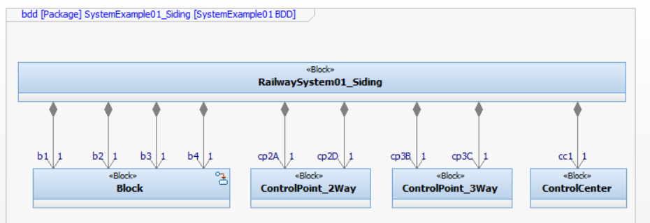
Figure 1 Railway Siding Example, block definition diagram showing composition (Rhapsody)
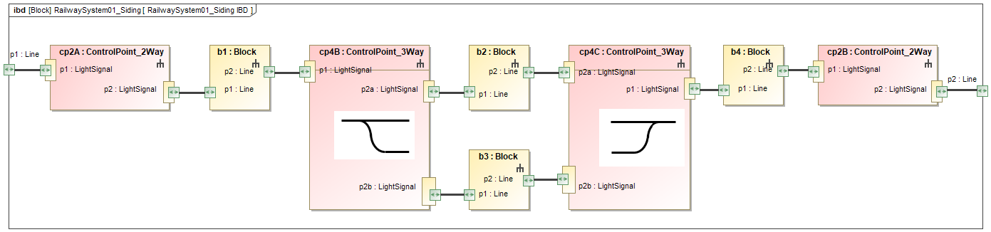
Figure 2 Railway Siding Example, internal block diagram showing track connectivity (MagicDraw)
A third diagram, another IBD, in Figure 3 shows the communication and control linkages within the subsystem from a new element of type ControlCenter. It is important to remember that all three diagrams are simply alternative views of the same model, not independent, unconnected figures. Even though they show different aspects of that model, they cannot be inconsistent because they are generated from the same source of truth.
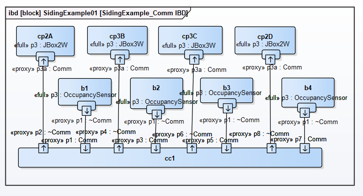
Figure 3 Railway Siding Example, internal block diagram showing control connectivity (Enterprise Architect)
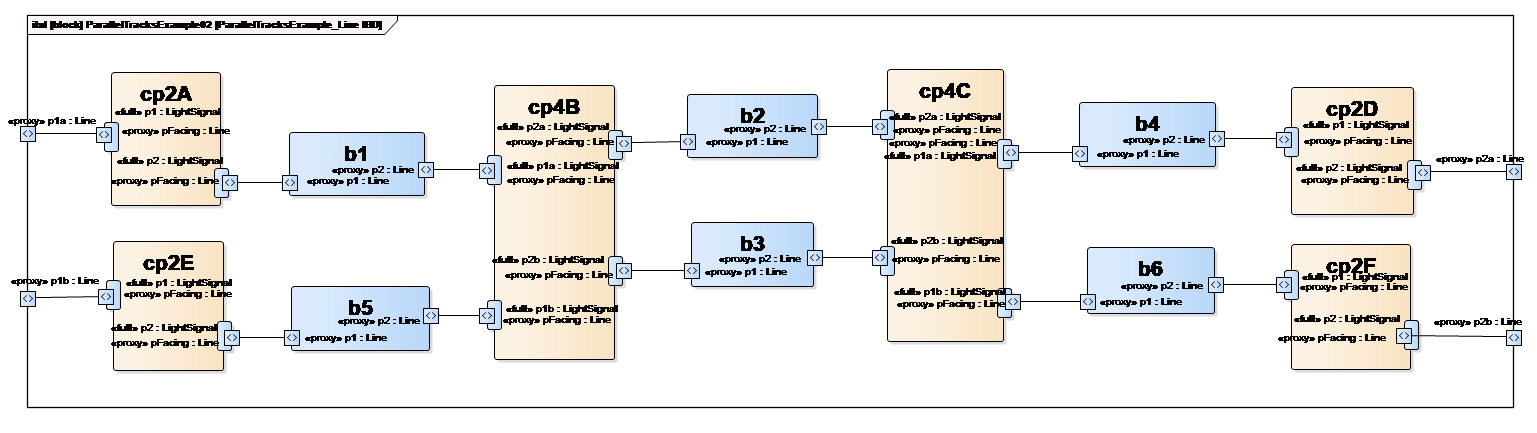
Figure 4 Parallel Tracks Example, internal block diagram showing track connectivity (Enterprise Architect)
A second subsystem example reuses many of the same system elements for two parallel tracks with two switchover points between them. In this case, we show only the track IBD in Figure 4, but the model includes the control network as well. In the same way, we can build up additional subsystem models quickly, which can themselves be used intact as parts of even larger systems.
Next Steps
At this point, the approach to building even larger structures is obvious, so we turn our attention to system behavior. The purpose of Computerized Traffic Control is to manage the dynamics of train movement via communications between switches, signal, sensors and an intelligent controller. In the next post, we shall show how SysML can be used to specify the sequence of messages allowing two trains to pass safely within the siding subsystem example, using interaction behaviors and sequence diagrams.
Related posts:
- Railway Control System Modeling | Part 1
- Railway Control System Modeling | Part 2
- Railway Control System Modeling | Part 3 (this post)
- Railway Control System Modeling | Part 4
- Railway Control System Modeling | Part 5
